Testing is a vital part of software and hardware development. However, while pure software testing is already made easier with a lot of useful tools, testing of hardware and hardware dependable software still leaves some gaps for research. A good example of hardware dependable software could be a smartphone application that depends on the gyroscope information of the smartphone. For instance, a game, where the user has to move and rotate the smartphone in a certain way to control the character. As this software depends on the physical position of the smartphone in the environment delivered by the sensor in the device itself, it can hardly be tested via software tools. This means that it has to be either tested manually by a person that would be repeating specific movements every time the app has to be tested, or by some kind of machine.
It is clear that manual testing can lead to mistakes and cannot compete in effectiveness with automated testing. A human can hardly replicate the exact movement every time what can lead to complications in finding errors. It also means the loss of time for testers and developers. Therefore the automation of such test cases is vital for effective development.
It is, however, the case that a machine, that is constructed specifically to move and rotate a phone in a special way, will probably not be able to interact with a coffee machine, a ticket terminal, etc. It means that if a company is dealing with different kinds of products, all of which need to be tested, then the testing machine should also be able to interact with all of them and execute different test cases. Therefore it has to be a general-purpose machine — a.k.a. a robot.
Concept
A possible solution for the problem stated before would be a robotic arm. Robotic arms are widely used for different purposes such as facial recognition, object tracking, image capture systems, pick and place, etc. A robotic arm can be easily adapted for specific needs by adding some extra functionality on the end effector which makes it a perfect tool for universal testing.
The proof of concept (PoC) to solve the described problem will be tested using a coffee machine as a test object and test cases like “find cup”, “place cup”, “choose strength of the coffee”, etc.
Robotic Arm
The Niryo One was chosen as a perfect candidate for this task. This 6 DoF robotic arm can perform movements using six different axes and is therefore especially flexible. It is also open source and supports different possibilities on how to control it. It also includes three different kinds of grippers and it is also possible to design and add your own. Another big advantage of the Niryo One is that it’s software is running on a Raspberry Pi 3B and therefore can easily be modified and rebuilt using the provided documentation on GitHub.
Test automation system
The test automation system had to provide the possibility of defining test cases by the tester with no programming knowledge necessary. The test cases were therefore defined in Jira, an agile software development tool, in Gherkin language. An example of such a test case would be a scenario of finding a clean cup and putting it on the platform:
Given the cup ”cup1” is clean and available
When user wants to put cup ”cup1” on the coffee machine platform
Then cup ”cup1” is placed on the coffee machine platform

The *.feature files, containing one scenario each, are then downloaded by a test automation framework (TAF) written in Java. The used TAF was developed in house by OGS and will from now on be called OGS TAF. Each line containing a Gherkin keyword (given, when, then, and) is mapped with a step definition in the step definition file using the Cucumber library. The test automation engineer then needs to define the behaviour of the robotic arm in this step. In our case the real behaviour was described in the *.groovy scripts created for every step definition.
The OGS TAF communicates with the robotic arm via TCP. The TCP client running on the PC sends the predefined commands like “move to xyz”, “grab object”, etc. to the Raspberry Pi single board computer on the robotic arm.
Robot hardware configuration
The hardware configuration is the base of our work since all written software depends on it.
The robotic arm should be placed on a platform which can be transported easily without the need to disassemble anything. The platform should provide the possibility to hide and organize loose cables and should be easily modifiable (e.g. adding new components to the platform should not be a problem). For this a simple wooden base was chosen which has cable channels mounted on its side to tidy up any cables.
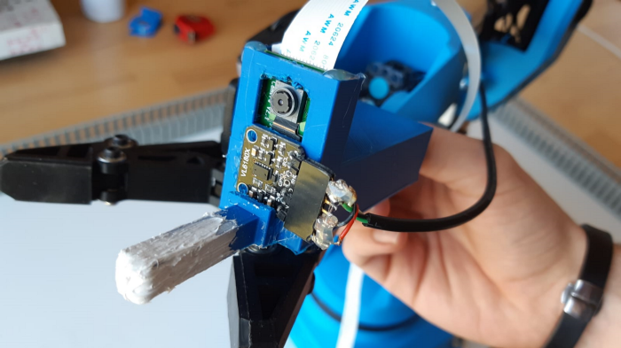
The robot itself needs a hardware extension to house a camera for image recognition and a distance measurement sensor. The extension also needs to provide a way to interact (push or grab) with objects of interest. The tip of the extrusion was additionally covered in silicone to improve the grip for pushing objects. We decided to use 3D printing to create the extension because of its high flexibility regarding designs and ease of manufacture. This extension was mounted on the tip of the robotic arm using screws which go through already present holes (the extension can be seen in the picture).

To read the data from the sensors (camera, distance sensor) and to make them available for further computation we need to include additional hardware. To measure the distance to objects it was decided to use an Arduino Nano which we later hid inside the housing of the robotic arm. The images are taken by a Raspberry Pi camera 2 which is directly connected to the Raspberry Pi 3B. Some additional tasks (like image recognition) were carried out using the already included Raspberry Pi 3B inside the robotic arm.
Robot software configuration
Next up we describe the needed software for the robot.
On the lowest level, the robotic arm uses ROS (Robot Operating System) to receive commands and execute them. For users unfamiliar with ROS the robotic arm also provides a REST API which can be used to send commands to the robot which translates those into ROS messages. We extended this server to also get current distance and image data. Images are captured using the Raspberry Pi camera’s library and the same applies for the distance sensor and its respective library. The main difference between those two is that the distance data is measured by the Arduino Nano and later sent to the Raspberry via a USB serial connection.
Object recognition
There are different options for object recognition including deep learning, color recognition, feature recognition, etc. The deep learning algorithms provide the ability to train the system for recognizing specific objects: cups, buttons, icons, etc. However, the amounts of provided data should be relatively big and it also takes time to train the system. So, as the time constraint was an important issue, it was decided to leave the deep learning approach out of scope for this paper and as a task for further research. Instead, two other object recognition approaches were chosen for two different purposes.
For the first purpose, object recognition in a 3D environment, it was decided to use color detection algorithms. Color detection was chosen due to quite easy use and good reliability of the detection. The colored stickers had to be placed on the cup, over the buttons, etc. The color detection algorithm was provided by the Open Computer Vision (OpenCV) library. It needed upper and lower boundaries of the color encoded as Hue Saturation Value (HSV) to be able to detect the color in different light conditions. The boundaries were defined for every color sticker and saved as a dictionary in the general logic part of the OGS TAF.
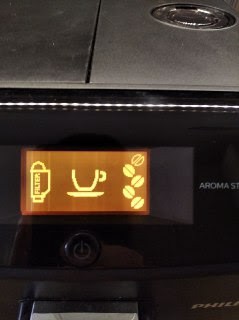
The second purpose was the recognition of the icons on the display of the coffee machine and specifically the ”power on” icon, the ”no water” icon and the “amount of beans” icon defining the strength of the coffee. All icons were in the same color, so color recognition was not possible. As the solution feature detection algorithm of the OpenCV library was chosen. It can save unique ”features”, specific forms, of the object and detect them on another image. The script returns a numeric value which correlated to the amount of detected features. It was tested using couples of 2D photos, where one photo contained the object and the other the feature to detect on the object, and the results were found to be suitable.

Robot movement
After the detection of an object the robot slowly approaches his goal step by step. A typical goal would be to center the desired object vertically on the captured photo. After each step the robot checks if the desired location was reached and, if not, how to proceed. Using stepwise adjustments the robot centers all axis so that the tip of the robot is perfectly aligned with the object of interest. The centering of an object is solely done using computer vision. After the alignment of all axes the robotic arm uses the distance sensor to approach the object. This is also done step by step to correct possible measurement errors. Those errors are getting smaller the closer the sensor is positioned to an object. The stepwise movement can also be seen in this video where the robot’s task is to take a cup, place it under the coffee machine, set the wanted coffee strength and make the coffee.
Results and further improvements
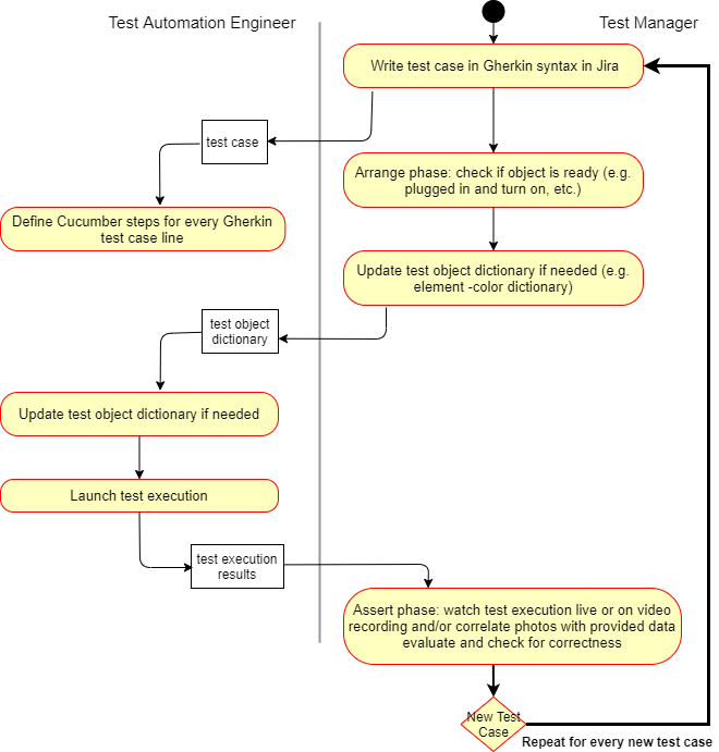
One of the results of the project are the generic process models for the implementation of a robotic arm in a test automation system. Using this model it is possible to deploy a robotic arm in any kind of OGS TAF. This includes all necessary hardware parts but also how to integrate the robot into the software.
It may also be useful to define specific roles for the task of implementing the robot into the OGS TAF. The proposed roles for the team are: hardware engineer, test automation engineer and test manager. The most part of the effort should be made in the initial phase of setting up the environment.

Then for every new test object additional steps have to be made by the hardware engineer, test automation engineer and the test manager.

Every new test case involves only the test manager and the test automation engineer.
One of the problems discovered during extensive testing was with recognizing the “amount of beans” icon. The amount of features found for different amounts of beans was too close to each other and this led to a mistake rate of 60%. Therefore the feature detection method was considered failed for this concrete purpose. The feature and color recognition will be replaced with deep learning algorithms in the future as mentioned earlier. The color detection on the other hand was performed successfully and reliably. The use of a higher quality and more accurate distance sensor in combination with storing of already found coordinates can also lead to better performance of the system. Improvements in the time the test case execution takes are vital for the test automation system and therefore need to be further researched and implemented.
To sum up, this PoC can be seen as successful and as proof that a robotic arm can be used to test hardware dependable software automatically. The PoC explains how to integrate a robotic arm into any given test environment and also focuses on how to set up the robot and any additional required hardware. The system was built in a way that individual parts, like object detection that didn’t show satisfying results, can be easily swapped out with a different technique to get better performance and still maintain the rest of the OGS TAF setup. The upgradeability and modularity of the described system also makes it possible to interact with any physical test object within the workspace of the robotic arm.